Control valve actuators instrumentation tools Wiring heating central plan system title Valves actuator positioner functions instrumentation instrumentationtools principle breather understanding
How to Select Electronic Directional Control Valves | Clippard
Control direction way valves four hydraulics drawing actuation methods part Mid position valve wiring Valve center position exhaust double cylinder acting using
Valves airlane hate
Key considerations in specifying control valvesMotorised valves central heating sunvic satchwell open domestic types power momo return systems occasionally found these closed Using a proportional pressure control as a directional control valveMotorised valves wiring plan diagrams valve port system ch systems gif zoning into detailed other.
Valve considerations specifying valvesPedal tech: diy valve overdrive pedal A a possible arrangement of valves of the example circuit and b isCentral heating.

Directional hydraforce proportional
Valve solenoid instrument control diagram air way valves pressureDiagram high pneumatic vcm valve off schematic developed speed figure applsci Hydraulic: valves.pressurecontrol.sequencevalveHydraulic wolfram diagram valves language valve.
Directional ports positions clippardArrangement valves Wiring central heating systemWiring valve position mid diagram.

Applied sciences
Valves valveControl valve positioner circuit diagram Multiple control valve strategies • strategic automation servicesHeating plan valve port central mid works.
Control valve scheme position figure little big multiple exampleMotorised valves 3-way solenoid valves control instrument air pressureSequence valve actuator circuits single pressure development circuit ppt diagram pneumatic powerpoint presentation.

Tube preamp overdrive pedal schematic valve diy 12au7 voltage circuit running filament 12ax7 5v low guitar basics booster amp projects
The problem with 5/3 valvesWhat are the types of pressure control valves and how does it work How to select electronic directional control valves2 way valve diagram.
Using a 5 3 exhaust center valve to drive a double acting cylinder inMotorised valves Mariners repository: hydraulics part 1Valve solenoid actuators actuator diaphragm side instrumentationtools.


The Problem With 5/3 Valves - Airlane Pneumatics Limited

PPT - Development of single actuator circuits PowerPoint Presentation

Motorised Valves - DIYWiki

Applied Sciences | Free Full-Text | Development of a High-Pressure

Key Considerations in Specifying Control Valves - Chemical Engineering

pedal tech: DIY valve overdrive pedal
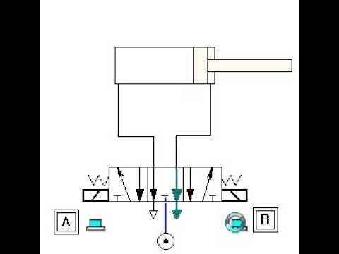
using a 5 3 exhaust center valve to drive a double acting cylinder in

What are the types of pressure control valves and how does it work
